
Introduction
This bulletin summarizes information specific to recycling dimethyl sulfoxide (DMSO), such that the process chemist or engineer can design and construct a system to fit specific conditions and requirements. Environmental aspects related to handling DMSO are also discussed.
Contents
DMSO Recovery
DMSO Recovery
Environmental Considerations
System Engineering
Foreword
Dimethyl Sulfoxide (DMSO) Recovery, System Engineering and Environmental Considerations
The intent of this bulletin is to provide the process chemist or engineer with a basic understanding of dimethyl sulfoxide (DMSO) recovery and information such that he or she can design and construct a system to fit specific conditions and requirements. Included is information regarding materials of construction and a typical recovery schematic diagram. Because individual system conditions vary widely, e.g., water concentration, impurity type and concentration, DMSO purity constraints, etc., this bulletin cannot cover specific system designs.
DMSO can be efficiently recovered from aqueous solutions, even though originally contaminated with volatile and/or nonvolatile impurities. Commercial users of DMSO employ a variety of processing schemes in their DMSO recovery system. All of these are based on evaporation or fractional distillation because of simplicity of design and operation. Unlike many polar solvents, DMSO can be easily separated from water by distillation in substantially pure form.
Recovery operations are generally designed on a basis of economics – balancing cost of solvent loss with capital and operating costs. However, air and water quality is becoming an important consideration in recovery design. Therefore, we have also attempted to answer environmental questions on DMSO in this bulletin.
DMSO Recovery
Separation from Aqueous Solution
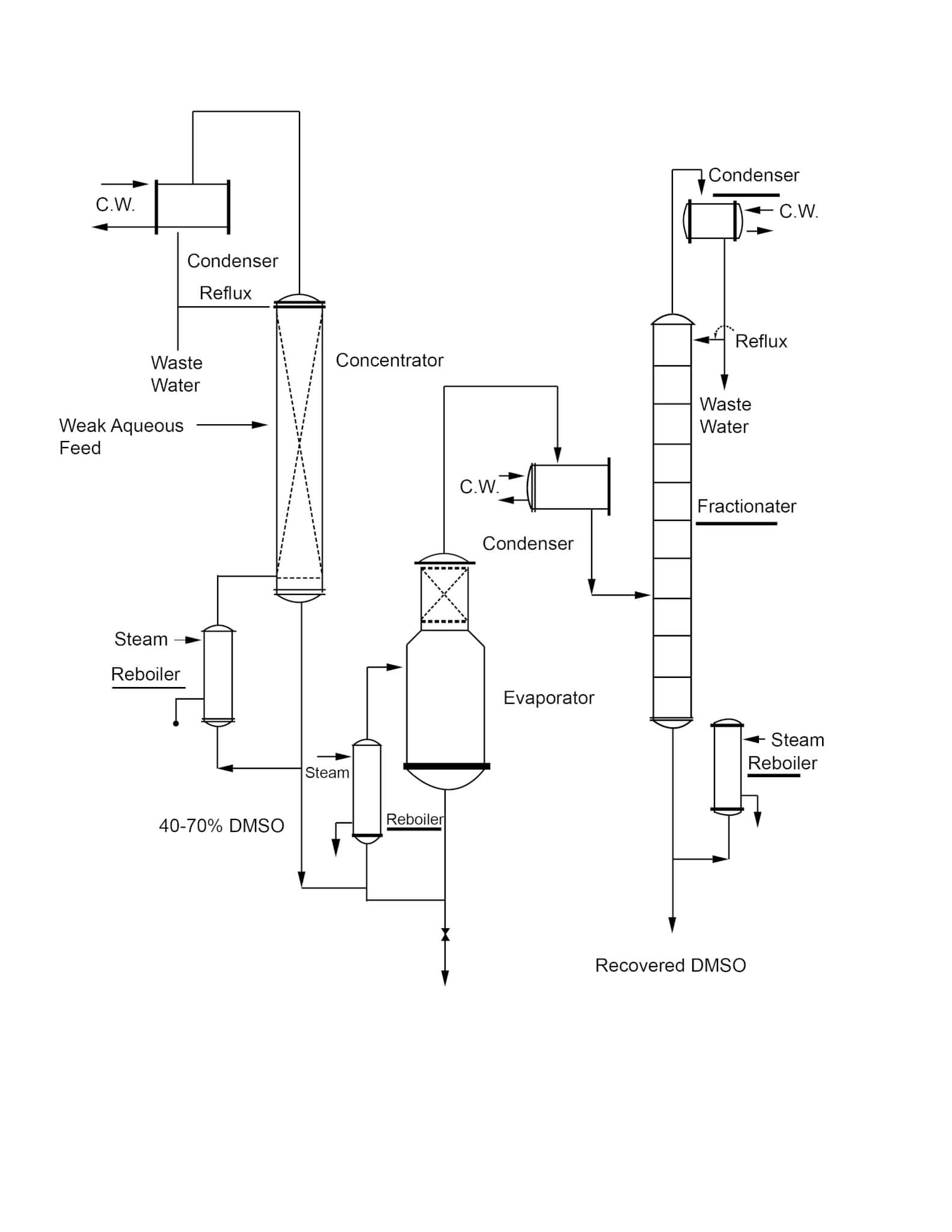
A typical feed to a recovery operation is relatively weak in DMSO – 10 to 20 weight percent. Therefore, there are usually three general steps in the operation:
- Concentration of the dilute DMSO-water solution to 40-70% DMSO.
- Evaporation of the DMSO-water solution overhead to eliminate non-volatile impurities, if any are present.
- Fractional distillation of the DMSO-water solution to recover pure DMSO.
Concentration of the dilute feed can be accomplished by: 1) simple evaporation, 2) stripping without reflux, or 3) fractionation with reflux. DMSO losses from simple evaporation will usually make this method less economical than the other two. A stripping column can operate with low DMSO losses and has some capital cost advantages over fractionation. A true fractionation with reflux reduces DMSO losses to a very low level and can be applied to a wide variety of recovery problems. For instance, in an application involving a volatile component such as methanol, it may be practical to recover this component as an overhead product during initial concentration.
The boiling point curves for DMSO and water are highly separated, particularly at high water concentrations. Therefore, plate and reflux requirements are minimal for the initial concentrating step.
Evaporation of DMSO and water from non-volatile impurities is usually conducted under some vacuum to lower the reboiler temperature. This is particularly recommended if done in a batch kettle. DMSO is most stable in neutral or slightly alkaline solutions. Therefore, pH adjustment prior to evaporation is recommended.
Final fractionation of the water overhead from the DMSO is usually done under vacuum so as to maintain a bottoms temperature in the range of 120 to 150°C. This again minimizes decomposition and allows the use of low pressure steam in the reboiler.
Some information on fractionator design is depicted in Figures 1 and 2. If one desires to obtain DMSO containing 500 ppm of water from the bottom of a continuous column while holding the DMSO content in the overhead water to 500 ppm, the number of theoretical plates required varies between 5 and 7 at a reflux ratio of 1 to 1 as shown in Figure 1. The lower Figure, 2, indicates the reflux ratios required to maintain these overhead and bottoms compositions if one has a column with 12 theoretical plates. Because of the relative volatilities of a DMSO-water system, distillation losses in a well-designed system should not exceed 1% of the DMSO feed. The overall recovery of DMSO will depend on the character and quantity of impurities present but should exceed 95-99% of the feed.
A typical recovery system is shown in the adjacent diagram (Figure 3). The continuous system shown is the most advantageous in terms of control and minimizing decomposition of DMSO.
DMSO is quite stable; however, the presence of contaminants such as inorganic acids afforded by continuous systems have advantages over batch systems.
Figure 1
Theoretical Plate Requirement DMSO/Water System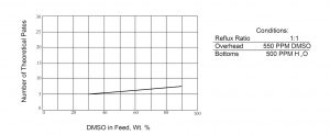
Figure 2
Reflux Requirement – DMSO/Water System
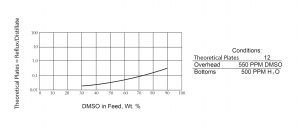
Figure 3
Typical System for Recovery of DMSO From Weak Aqueous Solutions
Removal of Nonvolatiles
Inorganic salts that may be present in the feed can be removed in a variety of ways. If the amount of salt is small, an intermittent purge from the evaporator is sufficient to clear the system without excessive loss of solvent. However, if large quantities of salts are fed to the system, other methods of removal should be studied. The two common methods used are centrifugation and thin-film evaporation.
Normally, the salts will accumulate and crystallize from solution in the evaporator bottoms. A slip stream from the bottom can be pumped continuously to a centrifuge. The salt crystals are spun out and the centrate is returned to the bottom of the evaporator.
With thin-film evaporation, the feed is pumped in at the top of a column having a heated shell. This would be used in place of the standard evaporator shown in the adjacent figure. As the material flows down the walls, it is thinned by rotating wiper blades and the DMSO and water is flashed overhead and condensed. The dried salt is discharged from the bottom. This method provides better DMSO recovery than the centrifuge technique. However, if the solids are pyrophoric when dry, special considerations in design should be made.
Tars and oils present in the feed can also be handled in various ways depending on their characteristics. One means of removing tar is to continuously remove a slip stream from the evaporator, dilute it with water to coagulate the tar and separate by filtration or decantation. The water and DMSO can be then returned to the feed. Oils and some tars can be removed as bottoms from a thin-film evaporator such as described above for handling inorganic materials.
Separation from Volatile Organics
There are no known azeotropes of DMSO and organic compounds. Therefore, fractional distillation provides a simple means of separating DMSO in pure form from volatile organics. Some data on binary and ternary systems with associated references can be found in Figure 4.
Figure 4
Separation from Volatile Organics
| System Type: Binary | Reference |
|
Methanol-DMSO |
Quitzsch, K. et al, Z. Phys. Chem. 234, 33-43 (1967). |
|
Dioxane-DMSO |
Ibid. |
|
Carbon Tetrachloride-DMSO |
Ibid. |
|
N-Butanol-DMSO |
Chandok, S. S. and McMillan, A. F. , J. Chem. Eng. Data, 14, 286-289 (1969). |
|
Isobutanol-DMSO |
Betancourt, T. and McMillan, A. F. , J. Chem. Eng. Data, 17, 311-313 |
|
Chloroform-DMSO |
Philippe, R. et al, Bull. Soc. Chim. Fr 2866-2871 (1971). |
|
Chloroform-DMSO |
Philippe, R. et al, J. Chem. Thermodyn, 5, 431-444 (1973). |
|
Methylene Chloride-DMSO |
Ibid. |
|
Bromoform-DMSO |
Ibid. |
|
Methylene Bromide-DMSO |
Ibid. |
| System Type: Ternary | Reference |
|
Benzene-Cyclohexane-DMSO |
Nissema, A., Ann. Acad. Sci. Fenn, Ser. A2, 153 (1970). |
|
Acetic Acid-Water-DMSO |
Bennett, C. F. , Crown Zellerbach Res. Memo No. 612-1 (1971). |
Environmental Considerations
Effluent handling from a DMSO recovery operation will, of course, vary with each installation due to differences in operating conditions and the amount and type of contaminants present. To assist the process designer, the following general information on environmental aspects is presented.
Air Quality
DMSO is highly stable at temperatures below 150°C. For example, holding DMSO at 150°C for 24 hours one could expect a loss of between 0.1% and 1.0%. Retention times even in batch stills are usually considerably less than this and, therefore, loss would be correspondingly less. These data also apply approximately to DMSO systems under alkaline conditions. However, under acidic conditions more rapid decomposition occurs and such conditions should be avoided.
The normal thermal decomposition products are formaldehyde, dimethyl disulfide, dimethyl sulfide, methyl mercaptan and water. The following equation approximates the reaction:

The volatile organic sulfur compounds, if formed and allowed to vent from reactors or stills, can be detected by their odor. The amounts of these are normally small and venting to an air dilution stack is usually sufficient. However, odors can be substantially removed by oxidative scrubbing of the vent gases with either potassium permanganate or sodium hypochlorite. Permanganate oxidation is more effective and faster than hypochlorite oxidation and allows greater operating flexibility.
Scrubbing Recommendations
If a known odor problem does exist, our engineers recommend the following possible methods:
Potassium Permanganate
The scrub liquor should be a strength of 2 wt % KMnO4. Sodium bicarbonate – about 2 wt % – should be added to buffer the solution to a pH of about 8.4. Carus Chemical Company’s literature (www.caruschem.com) describes the makeup of permanganate scrubbing liquids. A packed scrubbing column should have at least a 4-foot height. Liquid flow rate through the column should be at least 100 lb/hr per 1 lb/hr of DMSO decomposed. KMnO4 usage will be about 4 lb/lb of DMSO decomposed. Manganese dioxide, MnO2, forms as a solid and must be occasionally removed from the scrubber and recirculation surge tank. Carus Chemical Company’s literature also describes the operations of KMnO4 scrubbers and handling of MnO2.
Sodium Hypochlorite
The scrub liquor should contain about 12% available chlorine and have about 2% free NaOH. Commercial hypochlorite is available with these approximate specifications but it is more economical to make up the solution from chlorine and caustic. Counter-current flow is necessary in the column. Minimum packed height is 4 feet, but 10 feet is more desirable. Liquid flow rate through the column should be at least 200 lb/hr per 1 lb/hr of DMSO decomposed. Chlorine consumption will be about 3 lb/lb of DMSO decomposed.
The organic sulfur decomposition products should adsorb with fairly high loading on activated carbon, (Figure 5) although we are not aware of such an industrial practice with DMSO. Based on the method of Grant, Manes and Smith, AIChE J. 8, 403 (1962) gas phase adsorption at 25 °C should be approximately:
Figure 5
| Loading Lbs/100 Carbon* | ||
| Partial Pressure, 10 mm Hg | Partial Pressure, 100 mm Hg | |
| Dimethyl Disulfide | 45 | 50 |
| Dimethyl Sulfide | 28 | 34 |
| Methyl Mercaptan | 11 | 25 |
| *Pittsburg Activated Carbon Type BPL (4×10) B. | ||
Water Quality
DMSO purged from a recovery unit to a waste disposal system will slowly be converted by microorganisms to dimethyl sulfide (DMS) and dimethyl sulfone (DMSO2). The sulfone is stable and inert and degraded only slowly by microorganisms or physical factors. DMSO exhibits essentially no biochemical oxygen demand (BOD) because the molecule itself provides oxygen. Theoretical Oxygen Demand at 10 ppm is 123 mg oxygen. Chemical Oxygen Demand at 10 ppm is 107 mg/l and Biological Oxygen Demand-5 at 10 ppm is less than 1.0 mg/l.
If some of the volatile metabolite, DMS, is allowed to accumulate, odors may be detected. When such a situation exists, DMS formation can be easily prevented by oxidizing the DMSO in the effluent to DMSO2. DMSO2 is inert to biological action. A 1% aqueous solution of DMSO treated with 10% excess sodium hypochlorite, for example, oxidizes completely within 2 hours at 25°C. With 20% excess NaOCl at 40°C, DMSO at 1% oxidizes completely in 5 minutes. KMnO4 oxidation is even faster. Hydrogen peroxide oxidation is too slow to be commercially considered for weak aqueous DMSO solutions.
Liquid purge streams containing DMSO and DMSO2 can be handled in municipal or industrial waste treatment facilities without harm to the biological processes. Studies showed that 12,500 ppm DMSO or 7,000 ppm DMSO2, the highest concentrations tested, did not inhibit the activity of microorganisms from a waste treatment system.
Tests conducted on 19 species of fresh water plants and animals showed no apparent toxic effects (100% survival) at a level of 10,000 ppm DMSO. The tests, involving exposures of 6 to 24 hours included such species as early tadpole – Rama sp, rainbow trout – Salmo qairdneri, silver salmon – Oncorhynchus kisutch, pond snail, dragon fly nymph, duck weed and eel grass. No toxic effects were observed to 48-hour old Pacific oyster larvae challenged for six hours with 10,000 ppm of DMSO in sea water. The toxicity of DMSO2 was tested against rainbow trout fingerlings at 10,000 mg per liter. No toxic effects were noted during the four day exposure.
System Engineering
Materials of Construction
Metals
Although the data indicate that DMSO has a very low level of corrosivity, the product does darken considerably when exposed to mild steel, copper, brass, lead or zinc for long periods. Therefore, if color and purity are prime considerations, 304 or 316 stainless steel or aluminum are recommended metals of construction. Plant experience has shown that more than a 10-year life can be expected with stainless steel equipment under continuous exposure to DMSO-water solutions. Corrosion data on DMSO-water systems are shown in the following table.
Polymers
Because DMSO is a strong solvent, only a few polymer materials can be used under continuous exposure. Polyethylene, polypropylene and ethylene propylene rubber can be used at up to 120°F. Polytetrafluoroethylene (PTFE), such as a Teflon® grade, can be used up to the atmospheric boiling point of DMSO. Polyvinyl chloride (PVC), polyvinylidene chloride (PVDC) and most rubbers are not recommended. Tests should be conducted under design conditions if use of other polymers is contemplated.
Corrosion Data: Corrosion in Inches Penetration Per Month
| Metal | %DMSO | 22°C | 80°C |
| Mild Steel (ASTM A-285 Grade C) | 100 | <0.0001 | 0.0011 |
| 80 | <0.0001 | 0.0005 | |
| 50 | <0.0001 | <0.0001 | |
| 10 | 0.0001 | 0.0002 | |
| 304 Stainless | 100 | <0.0001 | 0.0001 |
| 80 | <0.0001 | 0.0001 | |
| 50 | <0.0001 | 0.0001 | |
| 10 | <0.0001 | 0.0001 | |
| 316 Stainless | 100 | <0.0001 | <0.0001 |
| 80 | <0.0001 | <0.0001 | |
| 50 | <0.0001 | <0.0001 | |
| 10 | <0.0001 | <0.0001 | |
| Aluminum (6061-T6) | 100 | <0.0001 | <0.0001 |
| 80 | <0.0001 | <0.0001 | |
| 50 | <0.0001 | <0.0001 | |
| 10 | <0.0001 | <0.0001 | |
| Nickel | 100 | <0.0001 | <0.0001 |
| 80 | <0.0001 | <0.0001 | |
| 50 | <0.0001 | <0.0001 | |
| 10 | <0.0001 | <0.0001 | |
| Monel (400) | 100 | <0.0001 | <0.0001 |
| 80 | <0.0001 | <0.0001 | |
| 50 | <0.0001 | <0.0001 | |
| 10 | <0.0001 | <0.0001 | |
| Copper (110) | 100 | <0.0001 | 0.0002 |
| 80 | <0.0001 | 0.0003 | |
| 50 | <0.0001 | <0.0001 | |
| 10 | <0.0001 | <0.0001 | |
| Titanium | 100 | <0.0001 | <0.0001 |
| 80 | <0.0001 | <0.0001 | |
| 50 | <0.0001 | <0.0001 | |
| 10 | <0.0001 | <0.0001 | |
| Lead | 100 | <0.0001 | <0.0001 |
| Zinc | 100 | <0.0001 | <0.0001 |
| Brass | 100 | <0.0001 | <0.0001 |
Process Equipment
Vessels and Tanks
Type 304L or 316L stainless steel is suggested for welded vessels and tanks. Aluminum type 6061- T6 has been used for wet and anhydrous DMSO, however, it is essential that the solution does not contain acidic or basic compounds.
To prevent DMSO from freezing (65°F melting point), a stainless steel coil is usually installed in storage tanks to keep the contents between 80° and 100°F. Hot water is suggested for circulation through the coil.
DMSO is hygroscopic, similar to glycerin. To keep DMSO anhydrous, atmospheric vessels and tanks may be vented through a dryer containing a suitable desiccant such as silica gel. The desiccant may be supported on a screen with the vent entering just below the screen and parallel to it. A drain (and cleanout) located in the bottom of the dryer may be useful. Carbon steel is satisfactory for the dryer construction.
Gaskets
Gaskets may be either the PTFE envelope type (ChempacTM 92, www.balfor.com) or as recommended in PTFE of 1/16″ thickness. Kalrez® perfluoroelastomer can be used in place of PTFE.
Pumps
Centrifugal pumps constructed of T304 or 316 stainless steel with John Crane Type 9, Code QP 191 mechanical seals are suggested.
Pipe and Fittings
For 3/4″ IPS and under, T304 or 316 schedule 40 pipe with 2,000 lb FSS screwed fittings are suggested. Two wraps of PTFE tape provide an effective sealant.
For 1″ IPS and above, T304 or 316 schedule I0S pipe with butt-welded seamless schedule l0S fittings are suggested.
Valves
Gate, globe or ball valves with PTFE packing are satisfactory.
Instruments and Tracing
Since DMSO freezes near room temperature, provisions should be made for tracing all pipe lines which carry anhydrous DMSO. Diaphragm sealed instrument pressure connections are recommended. Flange-mounted D/P cells are suggested for level transmission from tanks and vessels.
The information in this bulletin is based on information available to us and on our observations and experiences. However, no warranty is expressed or implied regarding the accuracy of this data, the results to be obtained from the use thereof, or that any use will not infringe any patent. Each user must establish appropriate procedures for off-loading, handling, and use of the product(s). Since conditions for use are beyond our control, we will make no guarantee of results, and assume no liability for damages incurred by off-loading, handling, or use of the product(s). Nothing herein constitutes permission, or recommendation to practice any invention covered by any patent without license from the owner of the patent.